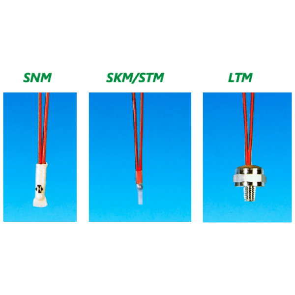
Small and flexible in use
- Ideal for limited installation space
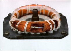
- Ideally suited for direct installation in and on windings
- An extensive range of stranded wires is available
- Multi-ling interconnections with up to 6 sensors in series are possible
Safe
- Manufactured according to DIN 44 081 (single sensor) and DIN 44 082 (triplet sensor) specifications
Reliable
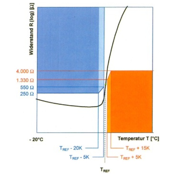
- Very high temperature sensitivity due to low mass
- In the range of the nominal response temperature TREF, the resistance R rises extremely steeply
Extremely durable
- No burn-off, no material fatigue, constant nominal response temperature (over years)
Supply voltage – DC voltage [V, VDC]
PTC motor protection sensors should ideally be operated with virtually no current. It is recommended to apply a voltage of approx. 2.5 V DC to 7.5 V DC, preferably pulsed. In this way, the power integral is minimised and the current flow through the PTC motor protection sensor is almost zero = > no or only very low self-heating!
A larger current flow can lead to self-heating of the sensor and thus to tripping even below the nominal response temperature TREF.
Multiple circuit:
In the case of multiple circuits, the total resistance is calculated from the sum of the individual resistances. The sensors are always connected in series!
Beispiel: Widerstand eines Drillings bei Raumtemperatur: 3 * ( < 250) = < 750 Ohm (Standard).
During installation, the PTC thermistor / PTC motor protection sensor
- As close as possible to the heat source
- be inserted parallel to the winding axis
- In the case of multi-phase motors, it should be installed in each winding if possible
Application
- In and on windings of electric motors, transformers or ballasts
- As a temperature sensor in devices (e.g. in the household or automotive sector, in electronic assemblies)
on heat sinks or circuit boards)
Hint
The data and information provided are based on tests and test series. They are intended as a guide, which is why there may be deviations for individual applications and uses. The suitability in a specific application must be checked by the user in each individual case.
Of course we will be happy to advise you.