CW1 |
SW1 |
CWK |
VW1 |
 |
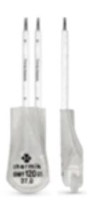 |
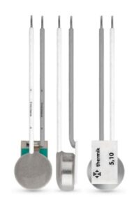 |
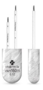 |
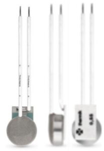
| Switch type: | NC contact CW1 | NC contact SW1 | Normally closed contact CWK | Normally closed contact VW1 |
| self-retaining , defined current-sensitive | ||||
| Insulated: with insulation protection cap | no | Yes | no | yes |
| Temperature | ||||
| Nominal switching temperature (NST), in 5 K steps [°C] | 60 – 160 | |||
| Tolerance range -Standard- Tol[ [K] | ± 5 | |||
| Reverse Switch Temperature (RST below NST) UL [°C]
Reverse Switch Temperature (RST below NST) VDE [°C] |
> 35
> 35 |
|||
| Tension | ||||
| Operating voltage range AC from … [VAC] | 100 to 250 | |||
| Rated voltage 50/60 Hz [VAC] | 250 (VDE), 277 (UL) | |||
| Current/switching cycles | ||||
| Rated current – cos Φ = 1.0 [A] / [n] | 2,5 / 1’000 | |||
| Rated current – cos Φ= 0.6 [A] / [n] | 1,6 / 1’000 | |||
| max. switching current – cos Φ = 1.0 [A] / [n] | 9,0 / 1’000 | |||
| Additional specifications | ||||
| Series resistors for setting the current sensitivity | from 0.12 Ω to 70 Ω | |||
| High-voltage resistance [kV] | — | 2 | — | 2 |
| Total bounce time [ms] | < 1 | |||
| Contact resistance (according to MIL-STD R5757) [mΩ] | < 50 | |||
| Vibration resistance 10 … 60 Hz [m/s2] | 100 | |||
| Suitable for installation in protection class | I | I + II | I | I + II |
| Impregnation resistance | suitable | |||
| Self-retaining with heating resistor RH (TB = 80 °C or 150 °C) | down to -20°C, freely suspended in still air. Correspondingly higher temperatures with thermal coupling. PTC heating resistor | |||
| Available Licenses and Approvals | ||||
| please specify | IEC, ENEC, VDE, UL | IEC, VDE, UL | IEC, VDE, UL | IEC, VDE |
| Dimensions (standard) | ||||
| Diameter Ø d [mm] | 9,0 | 9,4 | 9,0 | 9,9 |
| Overall height (with standard connection) h [mm] | from 5.1 | from 5.6 | from 5.1 | from 5.8 |
| Length of the insulation cap l [mm] | — | 18,0 | — | 19,0 |
| Standard connection wire: | Ø= 0.5 mm / AWG 22 | |||
| Functional circuit diagram – Standard – | ||||
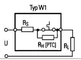
After the switch is opened, the current flows through the PTC heating resistor and heats the switch so that it remains in the off state until the voltage is removed. The series resistor is used to adjust the current sensitivity, as its heating causes the switch to trip earlier.
|
||||
| CW1 | SW1 | CWK | VW1 |
 |
 |
 |
 |
Note
The data and information provided are based on tests and test series. They are intended as a guide, which is why there may be deviations for individual applications and uses. The suitability for a specific application must be checked by the user in each individual case.


