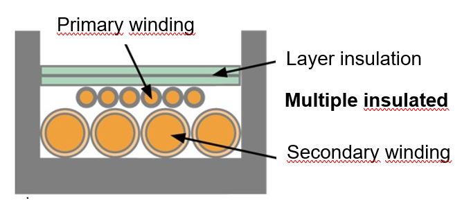
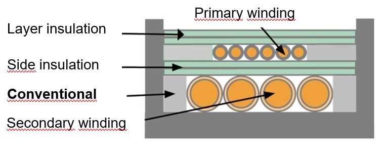
For applications with limited space for windings, where the slightly lower dielectric strength is sufficient.
| Conductor material: | tinned copper |
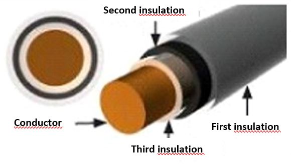
| Insulation: | Teflon® (FEP) |
| Number of layers: | 2 |
| Standard color: | — |
| Temperature class: | F (155° C) |
| Tensile strength: | 20.7 N/mm2 (3000 psi) |
| Conformity: | UL OBJT2 File No. E206198 UL/IEC60950-1 (Ed.2), Annex U, IEC 61010-1 (Ed.3), VDE Approval No. 6715: Class F |
| Solderability: | suitable for reflow soldering due to temperature resistance |
| Insulation thickness/layer: | 0,038 mm (0.0015“) | 0,51 mm (0.002“) | 0,76 mm (0.003“) | |||||||||
| Operating voltage: | 1000 | 1000 V | 1000 V | |||||||||
| Breakdown voltage: | ca. 8000 V | ca. 10000 V | ca. 13000 V | |||||||||
| Tolerancies: | ||||||||||||
| AWG | 18 – 24 | + 0,025/ – 0,025 mm | 18 – 24 | + 0,025/ – 0,025 m | 18 – 24 | + 0,025 / – 0,025 mm | ||||||
| AWG | 25 – 40 | + 0,025/ – 0,025 mm | 25 – 40 | + 0,025 / – 0,025 m | 25 -32 | + 0,025 / – 0,025 mm | ||||||
| Dimensions: | ||||||||||||
| AWG | Type | Conductor-Ø | Outer-Ø | Weight* | Type | Conductor-Ø | Outer-Ø | Weight* | Type | Conductor-Ø | Outer-Ø | Weight* |
| [mm] | [mm] | [kg/km] | [mm] | [mm] | [kg/km] | [mm] | [mm] | [kg/km] | ||||
| 10 | — | — | — | — | — | — | — | — | T10A01PXXX-3 | 2,588 | 3,045 | 51,25 |
| 11 | — | — | — | — | — | — | — | — | T11A01PXXX-3 | 2.304 | 2,761 | 41,08 |
| 12 | — | — | — | — | — | — | — | — | T12A01PXXX-3 | 2,052 | 2,510 | 33,09 |
| 13 | — | — | — | — | — | — | — | — | T13A01PXXX-3 | 1,829 | 2,286 | 26,64 |
| 14 | — | — | — | — | — | — | — | — | T14A01PXXX-3 | 1,628 | 2,085 | 21,40 |
| 15 | — | — | — | — | — | — | — | — | T15A01PXXX-3 | 1,450 | 1,908 | 17,35 |
| 16 | T16A01PXXX-1.5 | 1,290 | 1,519 | 12,74 | — | — | — | — | T16A01PXXX-3 | 1.290 | 1,748 | 14,02 |
| 17 | T17A01PXXX-1.5 | 1,151 | 1,379 | 10,24 | — | — | — | — | T17A01PXXX-3 | 1,151 | 1,608 | 11,44 |
| 18 | T18A01PXXX-1.5 | 1,024 | 1,252 | 8,02 | T18A01PXXX-2 | 1,024 | 1,328 | 8,56 | T18A01PXXX-3 | 1,024 | 1,481 | 9,31 |
| 19 | T19A01PXXX-1.5 | 0,912 | 1,140 | 6,62 | T19A01PXXX-2 | 0,912 | 1,217 | 6,92 | T19A01PXXX-3 | 0,912 | 1,369 | 7,61 |
| 20 | T20A01PXXX-1.5 | 0,813 | 1,041 | 5,16 | T20A01PXXX-2 | 0,813 | 1,118 | 5,61 | T20A01PXXX-3 | 0,813 | 1,270 | 6,25 |
| 21 | T21A01PXXX-1.5 | 0,724 | 0,953 | 4,16 | T21A01PXXX-2 | 0,724 | 1,029 | 4,58 | T21A01PXXX-3 | 0,724 | 1,181 | 5,16 |
| 22 | T22A01PXXX-1.5 | 0,643 | 0,871 | 3,34 | T22A01PXXX-2 | 0,643 | 0,947 | 3,72 | T22A01PXXX-3 | 0,643 | 1,100 | 4,27 |
| 23 | T23A01PXXX-1.5 | 0,574 | 0,803 | 2,72 | T23A01PXXX-2 | 0,574 | 0,879 | 3,10 | T23A01PXXX-3 | 0,574 | 1,031 | 3,57 |
| 24 | T24A01PXXX-1.5 | 0,511 | 0,739 | 2,20 | T24A01PXXX-2 | 0,511 | 0,815 | 2,51 | T24A01PXXX-3 | 0,511 | 0,968 | 2,99 |
| 25 | T25A01PXXX-1.5 | 0,455 | 0,683 | 1,79 | T25A01PXXX-2 | 0,455 | 0,759 | 2,08 | T25A01PXXX-3 | 0,455 | 0,912 | 2,53 |
| 26 | T26A01PXXX-1.5 | 0,404 | 0,632 | 1,46 | T26A01PXXX-2 | 0,404 | 0,709 | 1,73 | T26A01PXXX-3 | 0,404 | 0,861 | 2,14 |
| 27 | T27A01PXXX-1.5 | 0,361 | 0,589 | 1,19 | T27A01PXXX-2 | 0,361 | 0,665 | 1,44 | T27A01PXXX-3 | 0,361 | 0,818 | 1,85 |
| 28 | T28A01PXXX-1.5 | 0,320 | 0,549 | 0,98 | T28A01PXXX-2 | 0,320 | 0,625 | 1,22 | T28A01PXXX-3 | 0,320 | 0,777 | 1,58 |
| 29 | T29A01PXXX-1.5 | 0,287 | 0,516 | 0,82 | T29A01PXXX-2 | 0,287 | 0,592 | 1,04 | T29A01PXXX-3 | 0,287 | 0,744 | 1,40 |
| 30 | T30A01PXXX-1.5 | 0,254 | 0,483 | 0,67 | T30A01PXXX-2 | 0,254 | 0,559 | 0,88 | T30A01PXXX-3 | 0,254 | 0,711 | 1,22 |
| 31 | T31A01PXXX-1.5 | 0,226 | 0,455 | 0,57 | T31A01PXXX-2 | 0,226 | 0,531 | 0,76 | — | — | — | — |
| 32 | T32A01PXXX-1.5 | 0,203 | 0,432 | 0,48 | T32A01PXXX-2 | 0,203 | 0,508 | 0,67 | — | — | — | — |
| 33 | T33A01PXXX-1.5 | 0,180 | 0,409 | 0,41 | — | — | — | — | — | — | — | — |
| 34 | T34A01PXXX-1.5 | 0,160 | 0,389 | 0,34 | — | — | — | — | — | — | — | — |
| 35 | T35A01PXXX-1.5 | 0,142 | 0,371 | 0,30 | — | — | — | — | — | — | — | — |
| 36 | T36A01PXXX-1.5 | 0,127 | 0,356 | 0,25 | — | — | — | — | — | — | — | — |
| 37 | T37A01PXXX-1.5 | 0,114 | 0,343 | 0,24 | — | — | — | — | — | — | — | — |
| 38 | T38A01PXXX-1.5 | 0,102 | 0,330 | 0,21 | — | — | — | — | — | — | — | — |
| 39 | T39A01PXXX-1.5 | 0,089 | 0,318 | 0,18 | — | — | — | — | — | — | — | — |
| 40 | T40A01PXXX-1.5 | 0,079 | 0,307 | 0,16 | — | — | — | — | — | — | — | — |
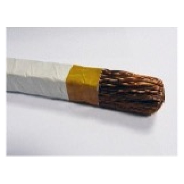
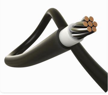
Individual AWG dimensions are also available as stranded wire.
![]()