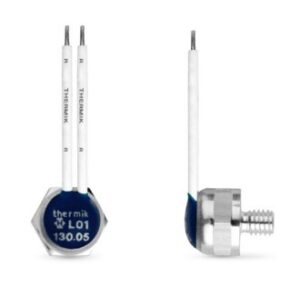
L01 |
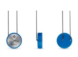
N01 |
 |
 |
| Switching mode | NC contact L01 resetting | NC contact N01 resetting |
| Insulated: Insulation cap | fully insulated | partially insulated |
| Temperature | ||
| Nominal switching temperature (NST) in 5 K steps °C | 60 -200 | |
| Tolerance range NST < 140 °C Tol (K) | + 5 | + 2,5 / + 5 |
| Reverse Switch Temperature (RST below NST) UL (defined RST possible on request) VDE |
– 35 + 15 ≥ 35 |
|
| Tension | ||
| max. operating voltage range up to … | 500 VAC / 14 V DC | |
| Operating voltage AC | 250 (VDE), 277 (UL) | |
| Current / switching cycles | ||
| Rated current – cos φ = 1.0 [A] / [n] | 2.5 / 1,000 1.6 / 10,000 6.3 / 3,000 7.5 / 3,000 |
|
| Rated current – cos φ = 0.6 [A] / [n] | ||
| Rated current – cos φ = 1.0 [A] / [n] | ||
| Rated voltage DC | 12 | |
| Max. Switching current DC [A] / [n] | 40’0 / 10’000 | |
| Additional specifications | ||
| High-voltage strength (kV) | 2 | — |
| Total bounce time (ms) | < 1 | |
| Contact resistance (according to MIL-STD R5757) (mΩ) | < 50 | |
| Vibration resistance 10 … 60 Hz (m/s2) | 100 | |
| Compressive strength of the switch housing (N) | 450 | |
| Suitable for installation in protection class | I + II | I |
| Impregnation resistance | suitable | |
| Available Licenses and Approvals | ||
| please specify | IEC, ENEC, VDE, UL, CSA, COC | |
| Dimensions (standard) | ||
| Diameter Ø d (mm) | 10,0 | 10,0 |
| Overall height h (mm) | from 7.0 | from 3.4 |
| Length of the connection pins (mm) | — | 14,0 / 20,0 |
| Thread (size x length) (M x mm) | M4 x 5.0 | — |
| Width across flats / max. Torque (mm / Nm) | 10,0 / 2 | — |
| Standard connection | Stranded wire 0.25 mm2 / AWG22 | Connection wire d = 0.5 mm |
| Characteristics of current dependence | ||
|
The special feature of the 01 and 02 series is that they are temperature-sensitive switches. In their rated operation (rated current), they exhibit very low self-heating due to the current. Therefore, a switching point reduction takes place at most within the nominal switching temperature tolerance.
|
||
L01 |
N01 |
 |
 |
Note
The data and information provided are based on tests and test series. They are intended as a guide, which is why there may be deviations for individual applications and uses. The suitability in a specific application must be checked by the user in each individual case.


