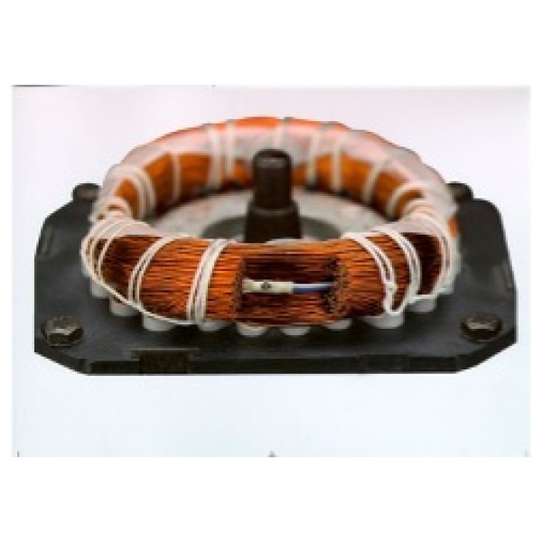
Small and pressure-resistant
- Ideal for limited installation space
- Excellent for mounting in and on windings
Safe, reliable, durable
- Constant contact pressure over the entire temperature range
- For type 06, H6, RH double contact switch-off (NC contact) / switch-on (NO contact) due to higher current intensity
- About 70 tests during production ensure quality
- Worldwide approvals
- Very fast switching; therefore short duration of the arc effect on the contacts
Temperature sensitive
- Reproducible switching temperature due to mechanically and electrically unloaded bimetallic disk, factory-set nominal switching temperature(NST)
Fast reaction time
- Good heat transfer to the rear derailleur due to very low switch mass
- With type P1 and W1 short switch-off times due to a defined series resistorRS
- Flexible use
- Wide supply voltage range with the exception of type R6,
- Extensive range of wires/strands
- For types P1 and W1, the heat output required for self-retaining is automatically regulated by a built-in PTC resistor RH (no overshoot)
Bimetal switch
When the factory-set nominalswitching temperature(NST) is reached, a bimetallic disk suddenly jumps from its stable starting position to a stable end position and actuates the rear derailleur.
Opener:
Types 01, Z1, P1, W1, 06, R6, H6, RH Contacts are disconnected and interrupt the circuit => direct switch-off
Closers:
Types 02, 08, 09 Contacts are closed and activate a circuit => e.g. activation of signaling devices.
Resetting:
Types 01,02, Z1, 06, 08, H6 If the temperaturefalls below the factory-set reset temperature(RST), the rear derailleur jumps back to its stable starting position.
Self-holding:
Types P1, W1 There is an integrated PTC heating resistor RH in parallel with the switching mechanism. After the contacts have opened, its heating power keeps the switching mechanism above the reset temperature until the supply voltage is interrupted. This function is used when automatic switching back after overheating and subsequent cooling is undesirable or not permitted. Check and/or service necessary!
Defined current sensitive:
Types Z1, W1
General Information
| Series | 01 | 05 | 06 | ||||
| Type | 01,02 | Z1, P1, W | 05,09 | 06,08,R6,H6,RH | |||
| T | Max. Pressure resistance of the housing (max. mechanical load) | 450 N (45 kg) | — | 300 N (30 kg) | 600 N (60 kg) | ||
| High-voltage resistance: | Version C | — | — | — | — | ||
| *Version S | 2kV | 2kV | 2kV | 2kV | |||
| Version L | 2kV | — | 2kV | 2kV | |||
| Version N | — | — | — | — | |||
| Version V | — | — | — | 3.75 kV | |||
| Version H | — | — | — | 2kV | |||
| Version P | — | — | — | 2kV | |||
| * | Suitable for installation for protection class
(insulation) |
I(1), II(2) | I(1), *II(2) | I(1), II(2) | I(1), II(2) | ||
| Protection class II – Type V – Standard | II(2) | ||||||
| * | Protection class | IP00 | IP00 | IP00 | IP00 | ||
| T | Impregnation resistance | suitable | Z1:suitable | suitable | suitable | ||
| Total bounce time | [ms] | < 1 | < 1 | < 1 | < 1 | ||
| Contact resistance
(according to MIL standard R 5757) |
[mW] | < 50 | < 50 | < 50 | < 50 | ||
| Vibration resistance
(at 10 … 60 Hz ) |
[m/s2] | 100 (10g) | 100 (10g) | 100 (10g) | 100 (10g) | ||
| * | Reset temperature range (RST) depending on switch family, on request | ||||||
| – Standard | [°C] | < 35 | < 35 | < 35 | < 35 | ||
| – UL standard range | [°C, K] | NST – 30 ± 15 | NST – 30 ± 15 | NST – 30 ± 15 | NST – 30 ± 15 | ||
| – CSA standard range | [°C, K] | NST – 10 … -50 | NST – 10 … – 50 | NST – 10 …- 50 | NST – 10 … – 50 | ||
NST= Nominal switching temperature
RST= Reset switching temperature
T after test by manufacturer
* others on request
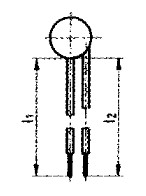
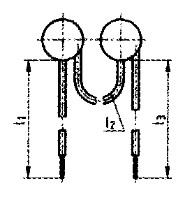
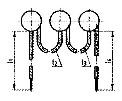
| Multiple wiring | |||
|
Individual wiring |
Twin connection | Triplet connection |
Conversion table |
 |
 |
 |
1 mm <=> 0.0394 inch (‘) 24.4 mm <=> 1 inch (‘) 100 mm <=> 3.94′ 300 mm <=> 11,91’ °C <=> (°F -32) / 1/8 |
Item number:
Example: TWDS01.130.05.0400/0180/0180/0650
Please always specify the desired approvals when ordering
| Version | Series | Nominal switching temperature NST | Tolerance range [± K] | Lengths mm] | ||||
| L1 | L2 | L3 | L4 | |||||
| Single with L1 = L2 | TW | S01. | 130. | 05. | 0300 | |||
| Single with L1 ¹ L2 | TW | S01. | 115. | 05. | 0300 | /0200 | ||
| Twin L1 – L3 | TWZ | S01. | 070. | 05. | 0200 | /0100 | /0200 | |
| Drilling L1 – L4 | TWD | S01. | 180. | 05. | 0400 | /0180 | /0180 | /0650 |
| L1 | L2 | L3 | L4 | |||||
Note
The data and information provided are based on tests and test series. They are intended as a guide, which is why there may be deviations for individual applications and uses. The suitability for a specific application must be checked by the user in each individual case. We will of course be happy to advise you.
![]()